How to Read a Multi-Page Wiring Diagram
Understanding a Multi-Page Wiring Diagram
An electrical wiring diagram can be a single page or several pages. It tells the installer how to connect the components and helps maintenance technicians troubleshoot the circuit.
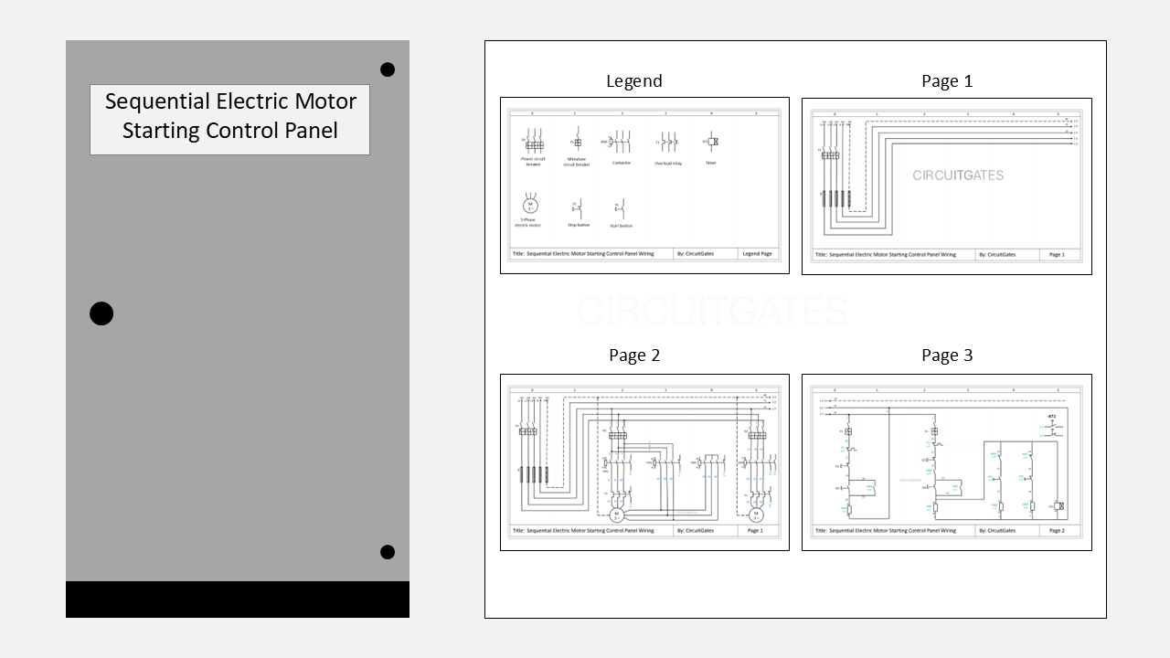
In this article, we will use a three-page sequential electric motor starter panel wiring diagram to explain, since the way of reading a wiring diagram is similar no matter how many pages it has.
The sequential electric motor wiring diagram is for two motors, one that is running on direct-on-line and the other on star-delta.
In this sequential electric motor starting, the star-delta control circuit is wired through the DOL motor control circuit, so that it only runs after the DOL motor starts.
There are a few things you needto know to understand a multiple-page wiring diagram. They are as follows.
1. First Familiarize Yourself With the Symbols Used
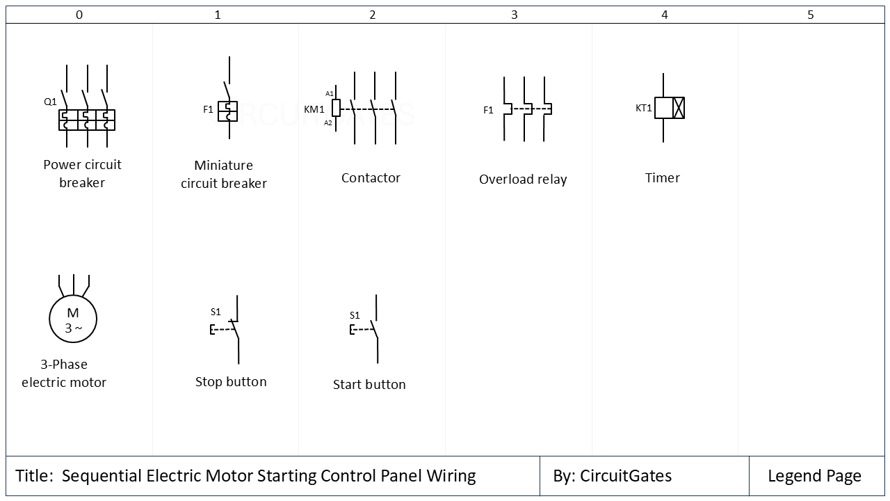
The first thing to do on understanding the multi-page wiring diagram is to familiarise yourself with the symbols in that wiring diagram.
Symbols of components differ depending on the circuit design software used to create the wiring diagrams, such as EPLAN, AutoCAD Electrical, and Siemens Capital X.
Electrical symbols for components are found on the legend page, which is usually among the first pages or the last pages of the wiring diagram.
In our previous multi-page wiring diagram, the first page shows the symbols of the components.
2. Direction for Reading Wiring Diagrams
Wiring diagrams are usually read from top to bottom and from left to right, although there may be situations that force designers to partly deviate from this rule.
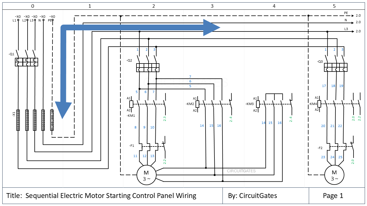
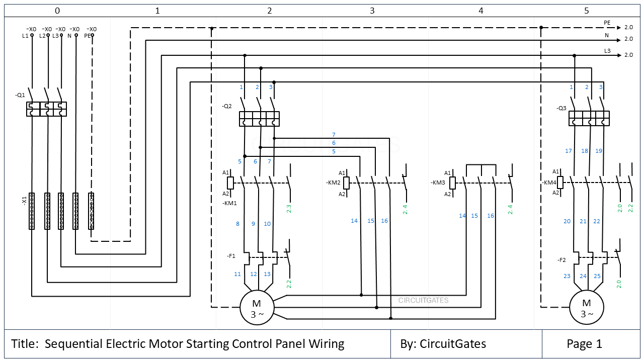
In the previous diagram, as we read from top to bottom and from left to right, we see that the supply to the panel is entering through the -X0 terminal strip.
From the terminal strip, the supply goes to the main circuit breaker (-Q1) . From the main circuit breaker, the supply goes to the distribution bars (-X1), from which power is taken to all other circuit components.
3. Addressing
Addressing involves identifying components on different pages of the wiring diagram and also identifying circuit components on the actual equipment or in the panels from the wiring diagram.
There are various methods used that enable addressing, including device tags, cable tagging, page numbering, and page column numbering.
i. Device Tags
Every device in wiring diagram is given a unique device tag. The device tag anables the electrician to identify the device on the actual equipment.
On page 1, the supply enters the panel through the terminal strip labelled -X0. From the terminal strip, the supply goes to the main circuit breaker labelled -Q1.
There are various prefixes used in wiring diagrams. The hyphen (-) prefix at the beginning of the device tag indicates that the tag represents a device according to IEC standards.
The letter just after the hyphen (-) prefix shows the type of device, as shown below. There may be a second letter to further specify the device.
- -Q - Main switch, e.g main circuit breaker or motor circuit breaker
- -F - Protective devices, e.g miniature circuit breaker, fuses, and overload relay
- -X - Terminals
- -K - Contactors, relays, and Timers
- -M - Motors
- -S - Switches and push buttons
- -C - Control cabinets/panels
Other prefixes used include +, = and :. The plus prefix (+) indicates physical location. It shows where a device is installed, such as a specific control panel or building floor if the building has several floors. For example, +OG1 means that the equipment is installed on the upper floor 1 (first floor) of the bulding.
ii. Cable Tags
The numbers at both ends of a cable shows where the cable is going to be connected. In our wiring diagram, the cable numbers are shown in blue.
Cables usually have cores and their cores also have tags that show where they are going to be connected.
iii. Page and Column Numbers
In wiring diagrams, devices can appear on several pages. In order to trace or locate a device on other pages, each page has a page number and is divided into columns.
Page and column numbers are used to locate devices on other pages. For example, in the top right corner of page 1; PE, N, and L3 have a 2.0 code after the arrows. The first digit "2", shows they are go to page 2, and the second digit "0" shows column 0. This means they go to page 2, column 0.
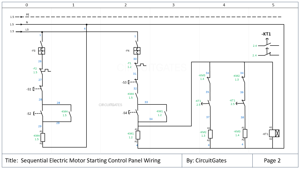
On page 2, you can see that at the beginning of the PE, N, and L3 supply conductors, there is a code "1.5", which shows they are coming from page 1, column 5.
On the contactor -KM2 on page 1, there is a contact with a code 2.4. This means this contact appears in page 2 and column 4.
If we go to page 2, we will find this contact with a label showing it apears on page 1.
Newsletter
Never miss a chance to learn something new with CircuitGates, subscribe to our newsletter
By subscribing, you agree to our Terms of use and Privacy policy.