Types of Electrical Drawings Found in Electrical Work
Electrical Drawings
In electrical work, different diagrams are used depending on the information that needs to be conveyed. These diagrams include layout diagrams, circuit diagrams, block diagrams, single line diagram and wiring diagrams.
Layout Diagram
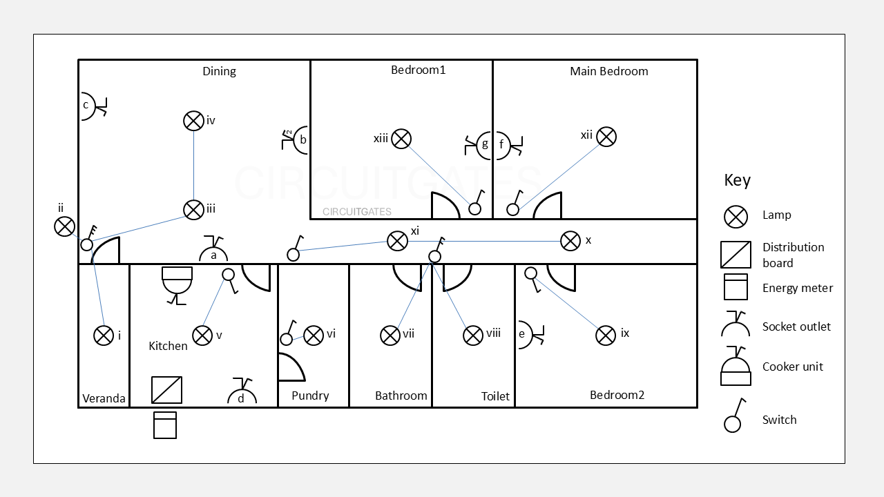
A layout diagram shows the physical placement of electrical components on a structure, device, or board.
The following layout diagram shows the physical placement of light bulbs, switches, cooker unit, energy meter, distribution board, and sockets on a house plan.
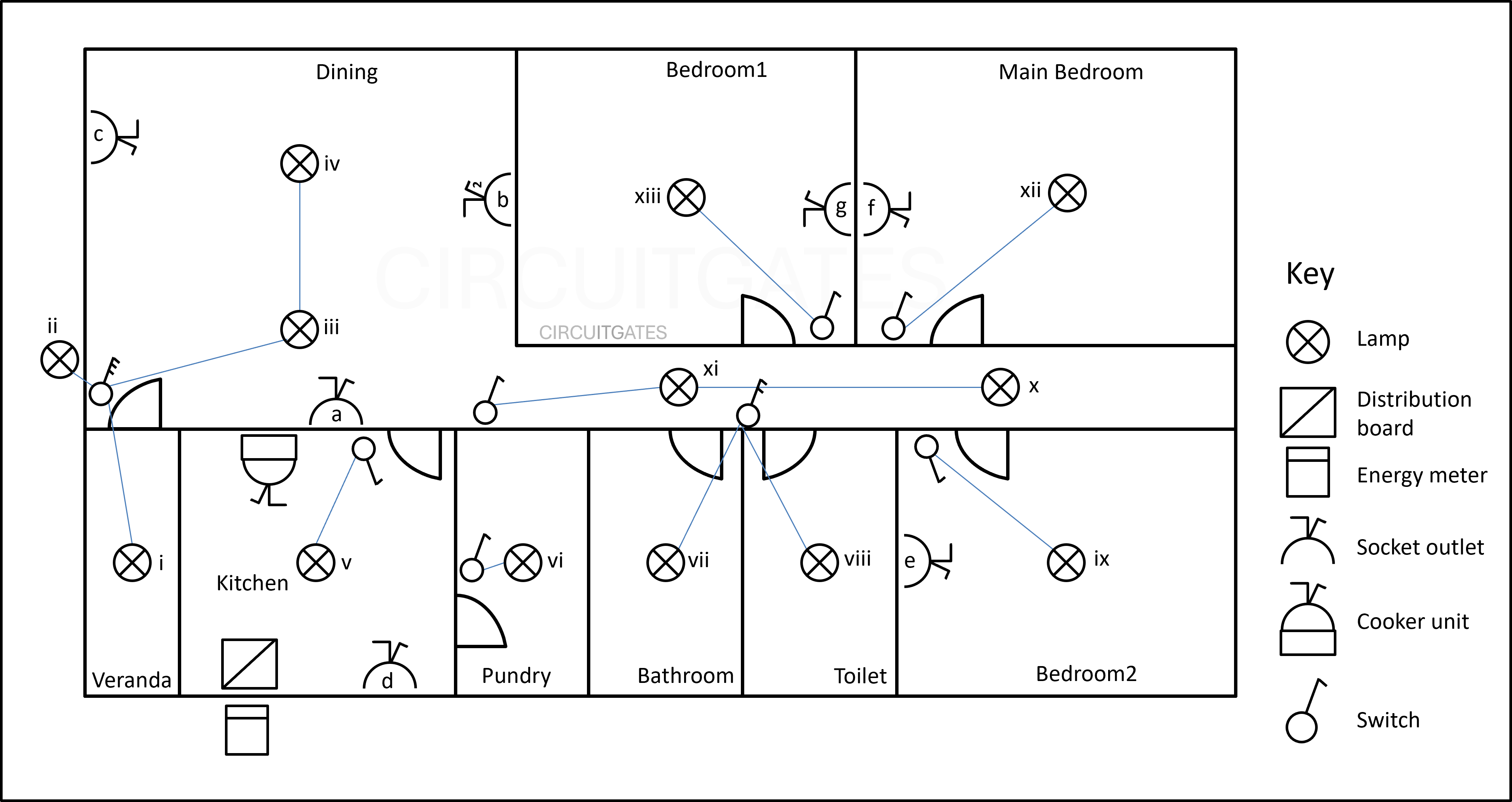
Layout diagrams are most important in new installations where the installer will want to know where to put the components.
Block Diagram
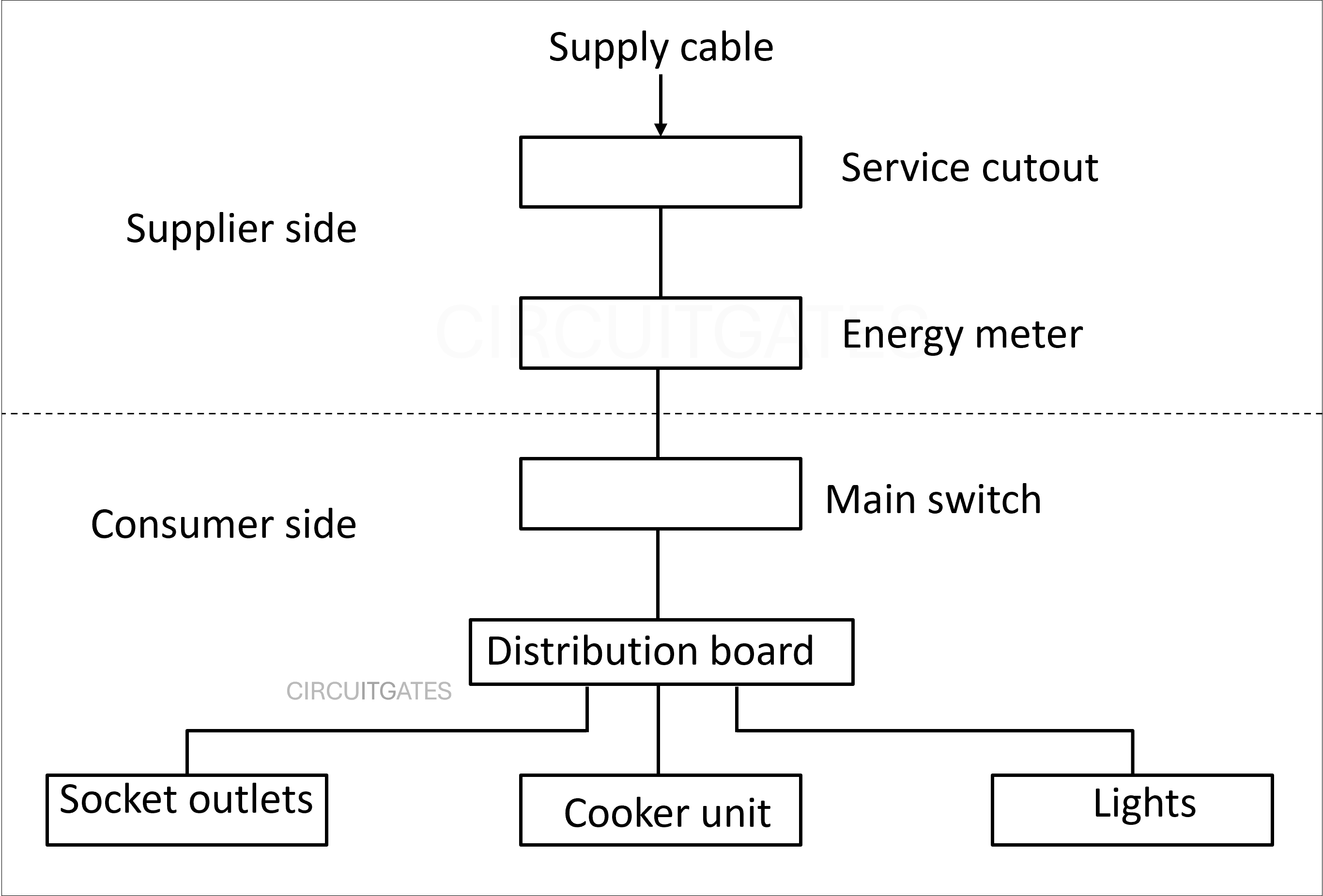
An electrical block diagram is used to show the flow of the system using shapes and lines connecting the shapes.
In the following diagram, the block diagram is used to show the flow of electricity in the domestic installation.
The shapes used in a block diagram usually represent devices in the installation, and lines are usually single .
Single Line Diagram
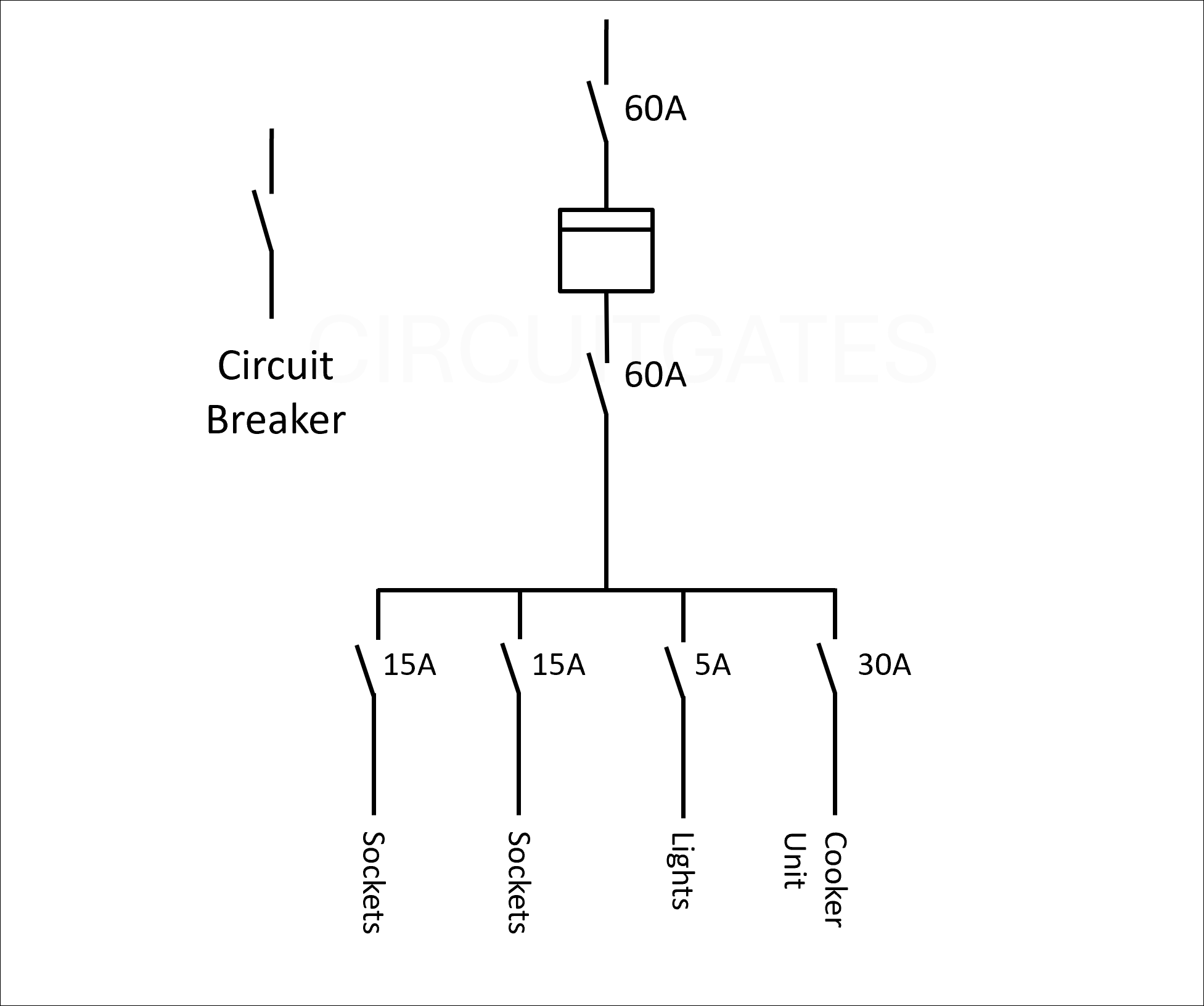
A single line diagram also shows the flow of electricity, using symbols connected by a single line.
A single line diagram shows information like the ratings and specifications of the components in the electrical system. It is more common in transmission systems.
In a single line diagram, the three phases, live, neutral or earth are shown using just one line.
Circuit Diagram
A circuit diagram or schematic diagram is mostly focused on showing how an electrical system works, helping electricians understand how electricity is moving in an electrical system.
The components in the circuit diagram are represented using symbols. The following diagram shows a circuit diagram of electricity supplied to the a house.
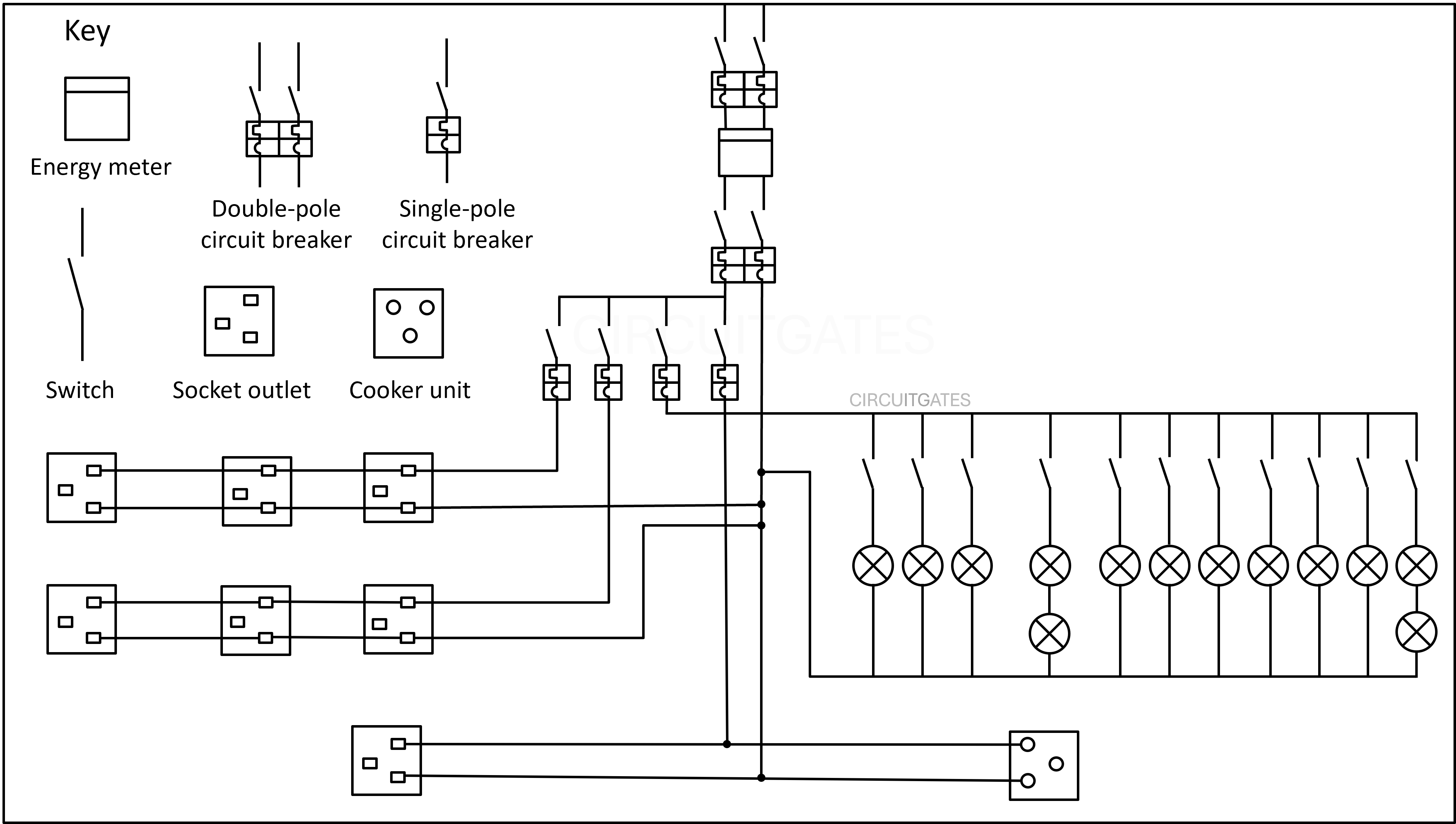
For some small installations, the circuit diagram can be used to wire the installation, but this is not its primary function
Wiring Diagram
Wiring diagrams show how the electricals system's components are connected, they are more focused on installation, setup, and trouble shooting.
Wiring diagrams and circuit diagrams are usually similar as both use the same symbols for components, but wiring diagrams have other additions.
The additions include device tags, wire tags and more that help the electrician to identify components in the field and connect the cables to the right components.
The following diagram shows a wiring diagram of a domestic installation.
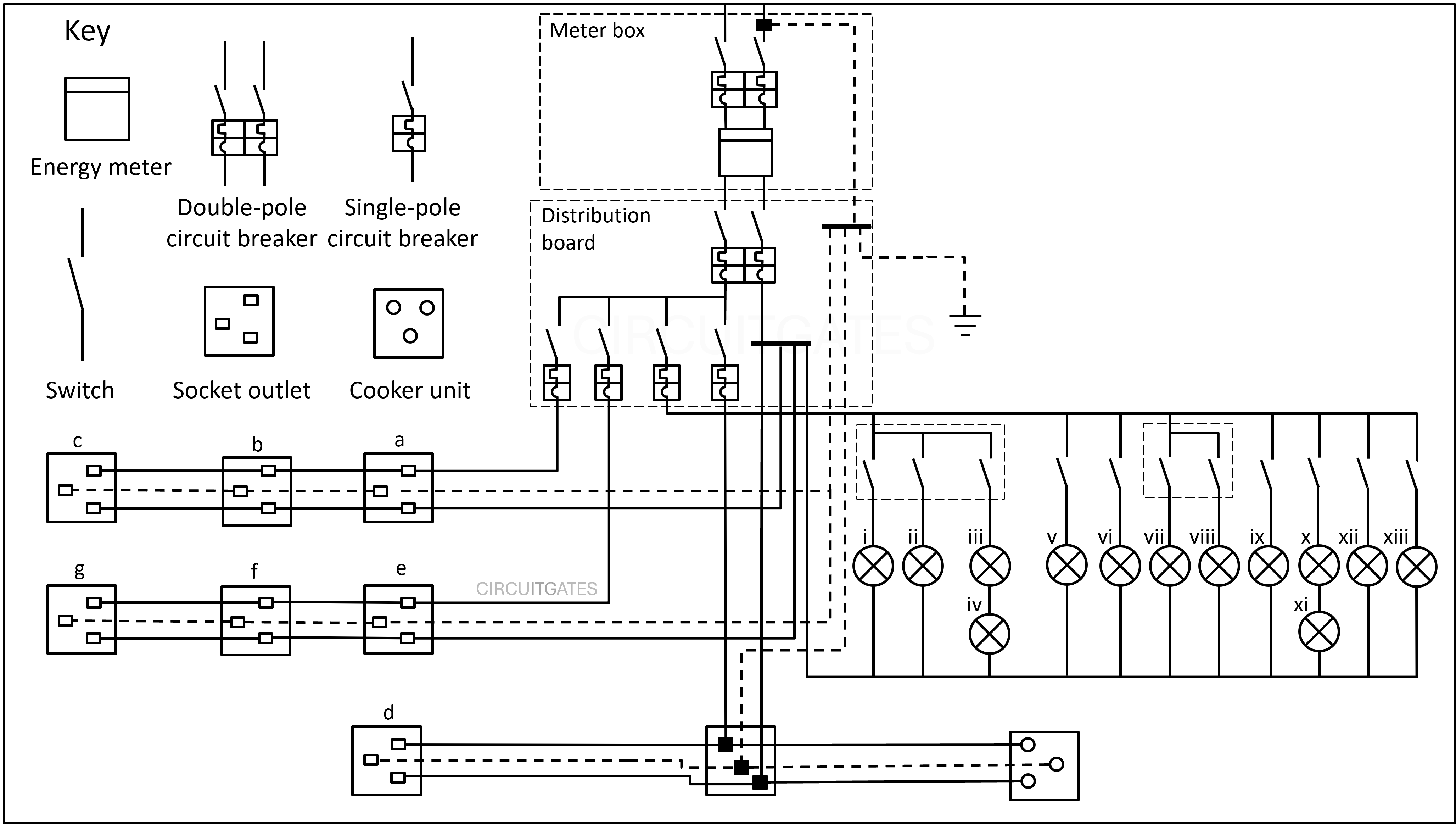
If you look at the wiring diagram closely and relate it to the previous layout diagram, you can see how the wiring is going to be done.
On the wiring diagram, we have not earthed the lamps because we are assuming that the fixtures and casings of the lighting circuits have no metal parts.
In the previous wiring diagram, we omitted several details because the diagram was for a small domestic installation. In a setup like this , it is easy to see where the cables are going.
In larger installations that contain a lot of cables and unfamiliar components, you will find several things on their wiring diagrams, such as device tags and cable tags. We cover these in more detail in a separate article.
Newsletter
Never miss a chance to learn something new with CircuitGates, subscribe to our newsletter
By subscribing, you agree to our Terms of use and Privacy policy.