What is Ladder Logic and How Ladder Logic Works

Introduction
Ladder logic is one of the programming languages used to write instructions that are followed by PLCs when controlling industrial processes.
An industrial process involves a number of machines working together to produce a certain product.
A PLC is a device used to control industrial processes. It mainly consists of input modules, a processor, and output modules.
Input modules receive signals from field devices like start and stop push buttons of the machinery a PLC is controlling.
Output modules send signals to output or field devices, such as relays and contactors of the machinery a PLC is controlling.
A processor reads the input signals, and based on the written instructions, it decides the sending of signals to the output devices of the machinery it is controlling through output modules.
Most electrical software vendors develop their own ladder logic programming languages that only work on their PLCs, but the working of these programming languages is the same.
Ladder logic is written in a ladder format, as shown in the following diagram, with the vertical lines called power rails and the horizontal lines called rungs.
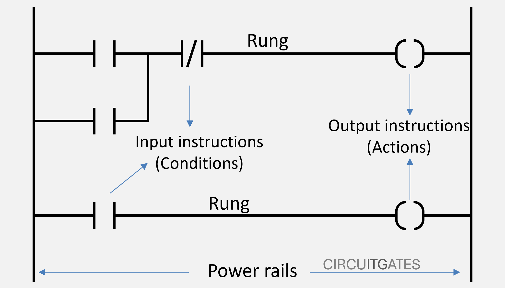
Power rails represent the power supply to the rungs, with the left power rail being live and the other on the right being neutral. Rungs represent PLC control circuits, with each rung representing an individual PLC control circuit.
A rung consists of input instructions written on the left side and output instructions written on the right side, as shown in the previous ladder logic diagram.
The PLC processor reads the rung from left to right and from top to bottom. The rungs work together to enable full control of processes.
How a PLC and Ladder Logic Work Together
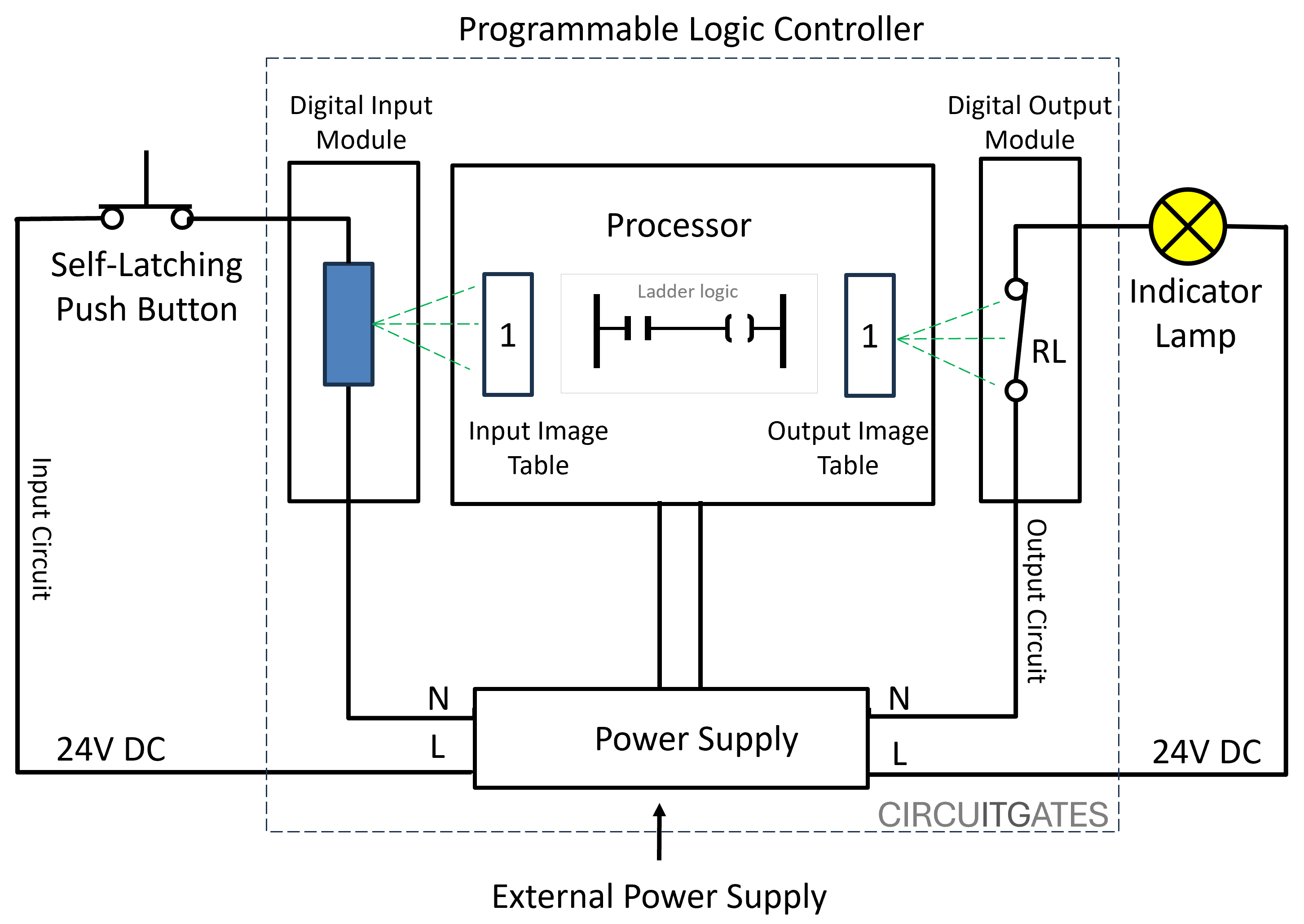
As we said earlier, a PLC consists of inputs, outputs, and a processor. The inputs and outputs of the PLC are not connected through hard wiring, but they are connected through a control program that is executed by the processor.
In the PLC memory, there is an input image table that stores bits of input circuits to the PLC. For every input circuit, the bit is stored either as 0 or 1, that is in discrete form.
The input image table is updated by the input modules and is where the processor gets the information about the conditions of the input circuits. The bit in the input image table corresponding to a specific input circuit is only set to 1 or true if that input circuit is energized.
The PLC also has an output image table that stores bits of output circuits from the PLC. For every output circuit, the bit is also stored either as 0 or 1, as shown in the following diagram.
For the output circuit to be energized, the bit corresponding to it in the output image table must be 1 or true.
What happens is, when the input circuit is energized or when current flows in it, the bit assigned to it in the input image table is set to 1, but if there is no electrical continuity in the input circuit, the bit remains 0.
In the PLC ladder logic program, for an output instruction to be executed, there must be a logic flow in the rung associated with it, just like in electrical circuits. In an electrical circuit, for a light bulb to turn ON, there must be a current flow or an electrical continuity.
The logic flow or logic continuity in a rung is determined by the conditions of the input instructions associated with it, just like in the light bulb circuit. For current to flow, all the switches associated with it must be in the ON position.
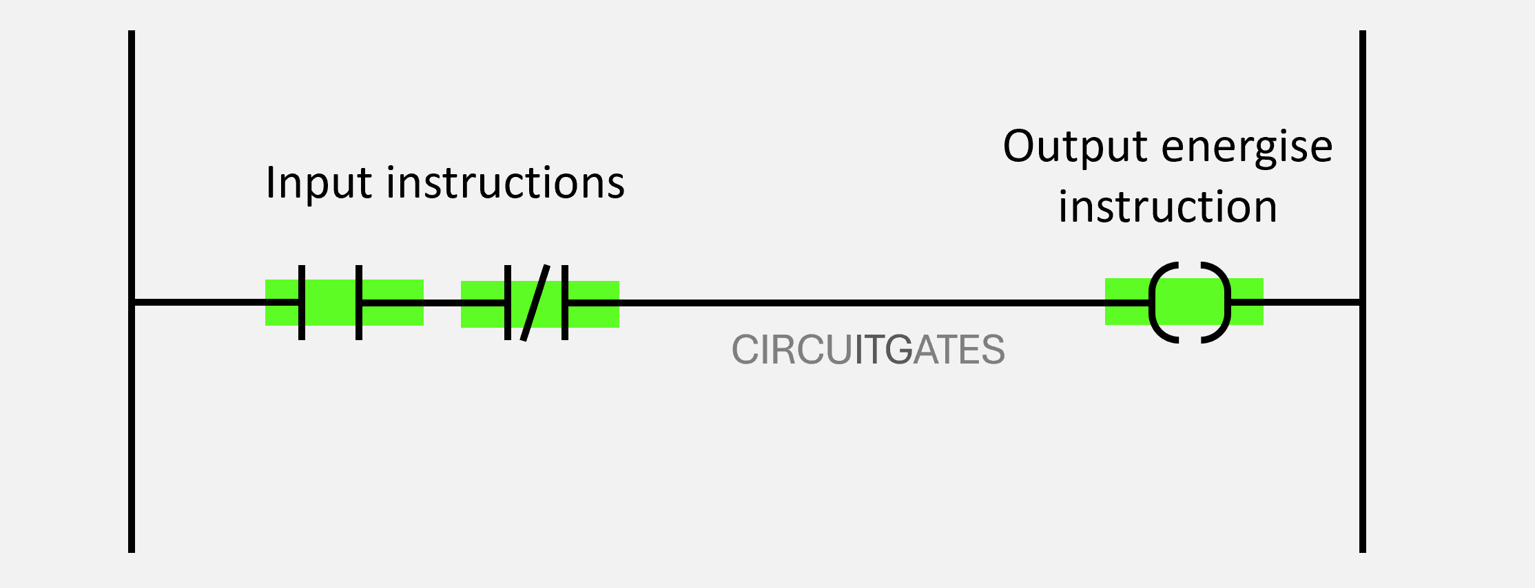
Depending on how the input instructions are connected - for example the series connection in the following diagram - all the input instructions must be true to have a logical continuity in the rung and for an output instruction to be executed. When the input instruction is true, it is shown by green shading.
The processor of the PLC constantly checks the conditions of the input instructions to the bits in the input image table. If the condition of an input instruction is true, it will be allowing logic flow.
Input Instructions
In a ladder logic program we have two main input instructions: normally closed instruction and normally open instruction. The conditions of input instructions can be either true or false (0 or 1).
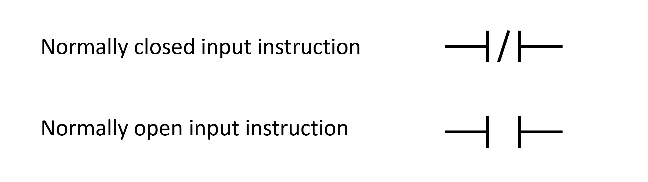
The Normally Open Input Instruction
The normally open input instruction is also called examine if close instruction (XIC), or the examine on instruction. The examine if closed instruction is only true if the bit in the input image table is 1.
The normally open input instruction is used to check if the bit in the input image table becomes 1, or if the input circuit associated with it is energized. The check if close instruction is only true if the bit is 1, if the bit is 0, it is false.
The Normally Closed Input Instruction
The normally closed input instruction is also called examine if open instruction (XIO), or the examine off instruction. The examine if open instruction is only true if the bit is 0.
The normally closed input instruction is used to check if the bit in the input image table remains 0 or if the input circuit associated with it is not energized. The check if open instruction is only true if the bit is 0; if the bit is 1 it is false.
If the normally closed input instruction is true or the bit associated with it is 0, it maintains its closed position, allowing logic flow in the rung.
NB: The bits in the input and output tables, the input and output instructions and the rungs can be written as true or false, or as 0 or 1. To minimize confusion in this article, we are going to use 0 or 1 for bits in the tables, true or false for instructions, and logic continuity for rungs.
Output Instructions
Output instructions are located on the right side of the ladder logic diagram. Output instructions are only executed when the rung has logic flow.
The output instructions update the output image table. The output PLC circuit is only energized when the bit associated with it is true. We have several output instructions that include output energize instruction, set coil instruction, and reset coil instruction.
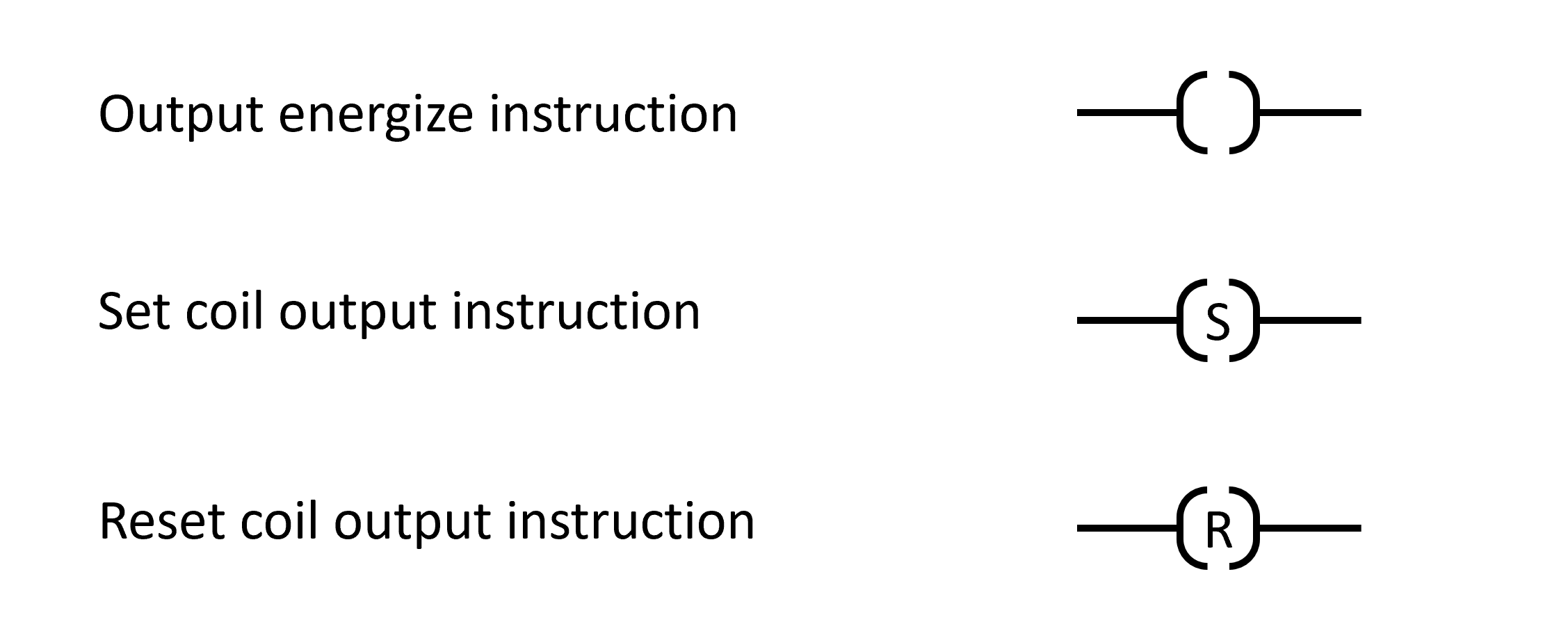
Output Energize (OTE)
Sets the bit in the output image table to '1' when the rung has logic continuity. When the rung has logic continuity, the bit in the output image table is set to '1' and the output circuit is energized.
Set Coil
Sets the bit in the output image table to '1' when the rung is true and keeps it set until a reset instruction is executed.
Reset Coil
Resets the bit in the output image table to '0' when the rung is true.
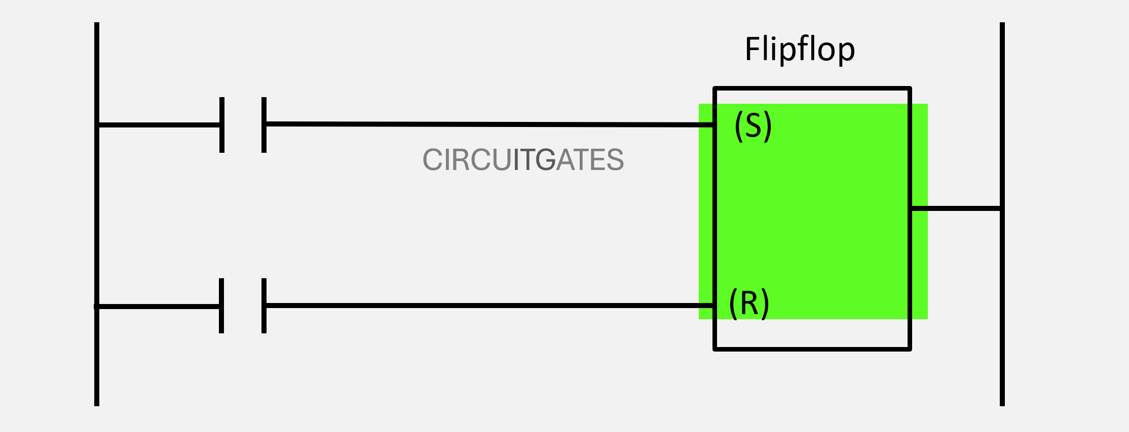
The set and reset coils usually work together to enable complex process control. In the following diagram, the set coil sets the output bit to 1 when the rung associated with it has logic continuity and keeps it to 1 even when the rung loses its logic continuity.
The output bit is then used to reset the bit to 0 when the rung associated with the reset output instruction has logic continuity.
Connecting Input Instructions and Rung Continuity
Each rung in ladder logic must at least start with one input instruction and ends with at least one output instruction.
While it is common to use a normally open input instruction for the input circuit that contains the normally open field devices such as the start button, the normally open input instruction will be reading the bit associated with the input circuit containing that start button. The instruction is not representing the start button.
In a ladder logic program, a rung can have one or more input instructions. When connecting input instructions, we either connect them in series, in parallel, or a combination of both.
The following rungs contain input instructions wired in series and in parallel, respectively.
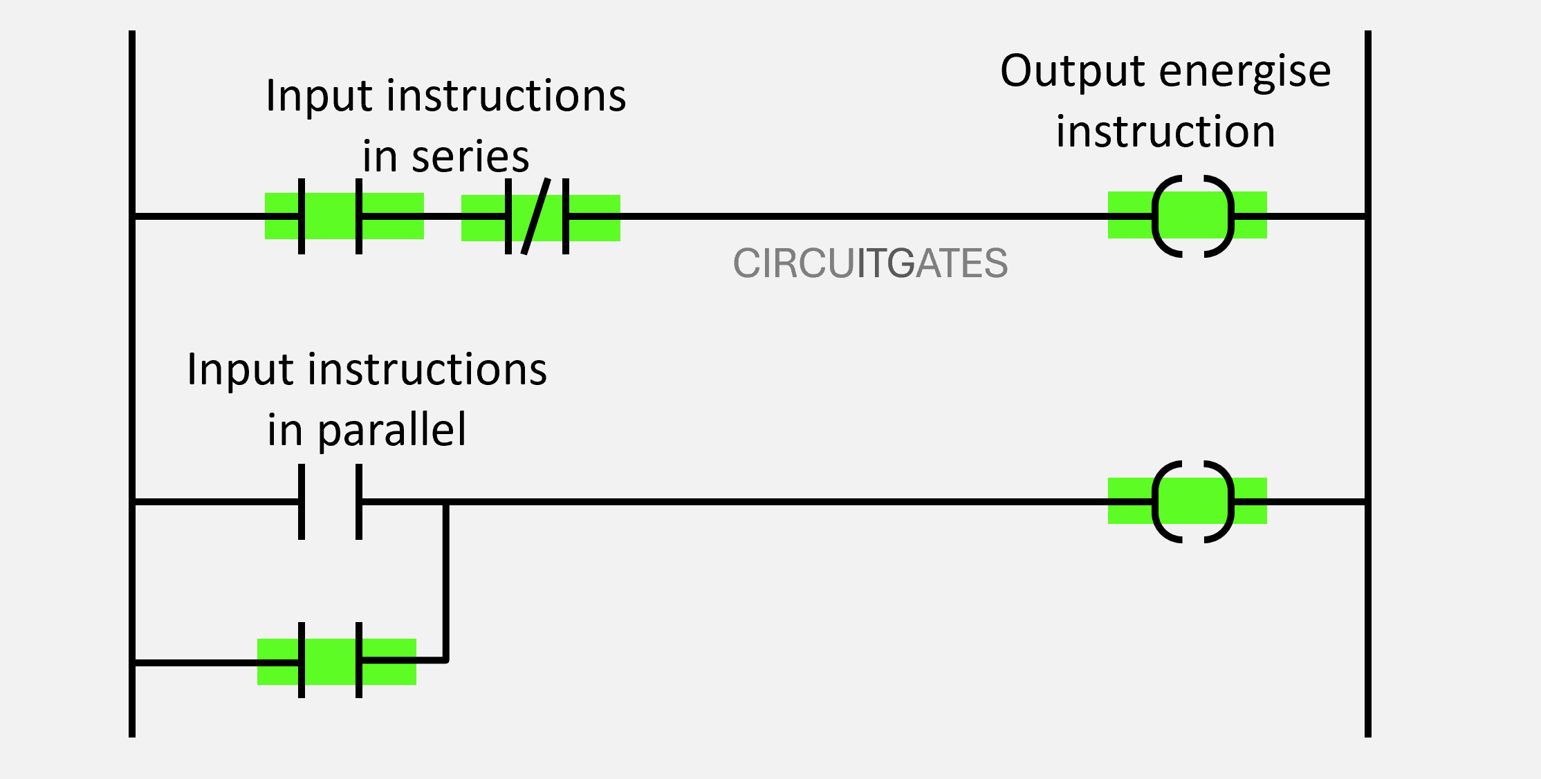
When having two or more input instructions in one rung, depending on the connection used, their conditions will determine the condition of the rung. A rung can either have logical continuity or not.
When the rung has logical continuity, an output action occurs, but when the rung has no logical continuity, no output action occurs. Connecting two or more input instructions follows a certain logic function that determines the condition of the rung.
Logic functions commonly found in ladder logic include AND, OR, XOR and NAND.
Before connecting input instructions in a rung, you need to first decide which logic function to use. The following are logic functions commonly used in ladder logic programs
Logic Functions
AND
Is a logic function that gives a rung logical continuity when all the inputs are true, if one input is false or all are false, it gives no logical continuity to the rung and the output action does not occur.
The zeros represent FALSE and the ones represent TRUE. In the following diagram, all inputs are true, as shown by green markings, and the action occurs on the output.
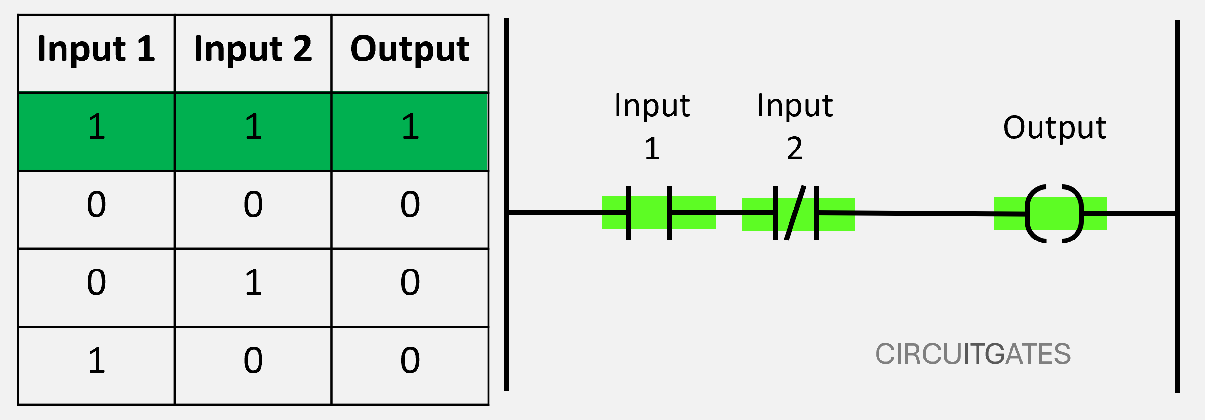
The AND logic function is used on inputs connected in series, as shown in the previous diagram. In a series connection of inputs, the rung only has logical continuity when all inputs are TRUE.
OR
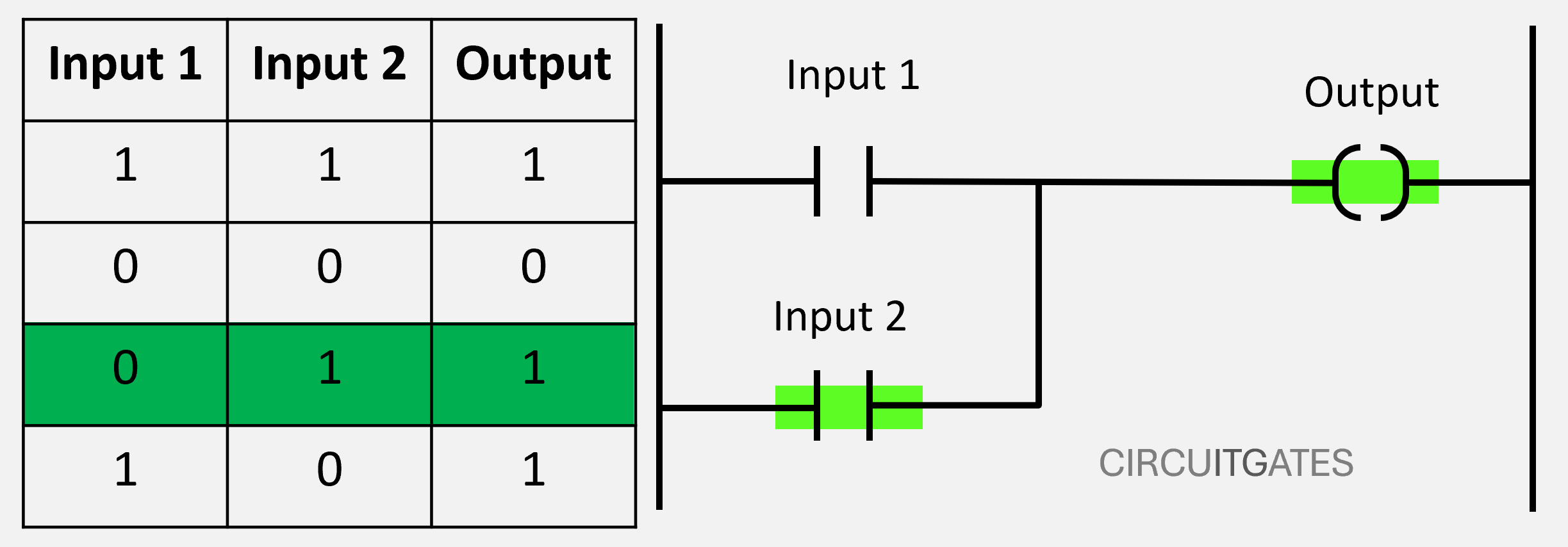
Is a logic function that gives a rung logical continuity when one or all inputs are true. The OR logic function is used on inputs connected in parallel, as shown in the following diagram.
In a parallel connection of inputs, the rung only has logical continuity when one or all inputs are TRUE. In the following diagram, one input is true, as shown by the green marking and the action occurs on the output instruction.
Instructions Appearing in More Than One Rung
In a ladder logic program, an instruction can appear in more than one rung. For example, an output instruction can appear as an input instruction on another rung or in that rung.
In some scenarios, we can have an input circuit to the PLC that contains a device that returns to its normally open position after pressing it, like the start button.
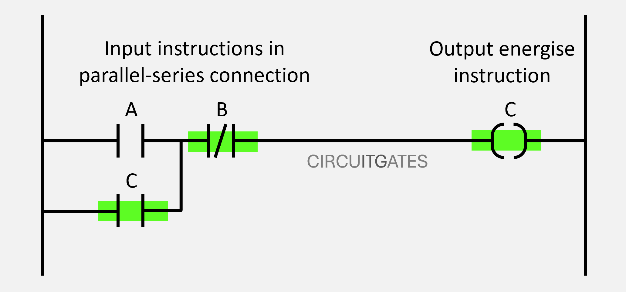
While we want the rung to continue having logical continuity after pressing this device, we want to cancel rung continuity after pressing the stop button.
This is achieved by wiring the output instruction as an input instruction of the same rung in parallel with the normally open instruction, as in the previous diagram. In this way, the rung will continue having a logical continuity since the output instruction is working as an input instruction held in.