How Sequential Electric Motor Starting Works
Sequential electric motor starting involves the starting of two or more electric motors, one after the other in an orderly way.
The sequential electric motor starting is most applicable in situations like production processes that involve several stages.
In production processes, there are some stages that need to run first before others. When the stages that are supposed to run first stop working, others that follow must also stop.
For example, in production of gravel, let us start with the stage of crushing rocks into gravel used in construction using the crushing machine.
After crushing, the produced gravel needs to be moved to a certain place for storage using a conveyor belt.
In this example, the electric motor used to turn the crushing machine uses a star-delta starter. The other one that is moving the conveyor belt uses direct online starter (DOL).
Since after crushing the rocks, the gravel needs to be moved away from the crushing machine by the conveyor belt to prevent accumulation of gravel on and in the crushing machine. This is where the sequential electric motor starting comes into action.
In sequential electric motor starting, the conveyor belt electric motor runs first before the crushing machine electric motor runs. Also, if the conveyor belt electric motor stops working, the crushing machine must also stop working.
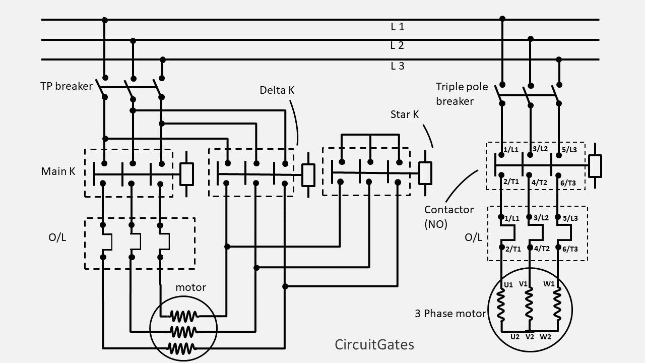
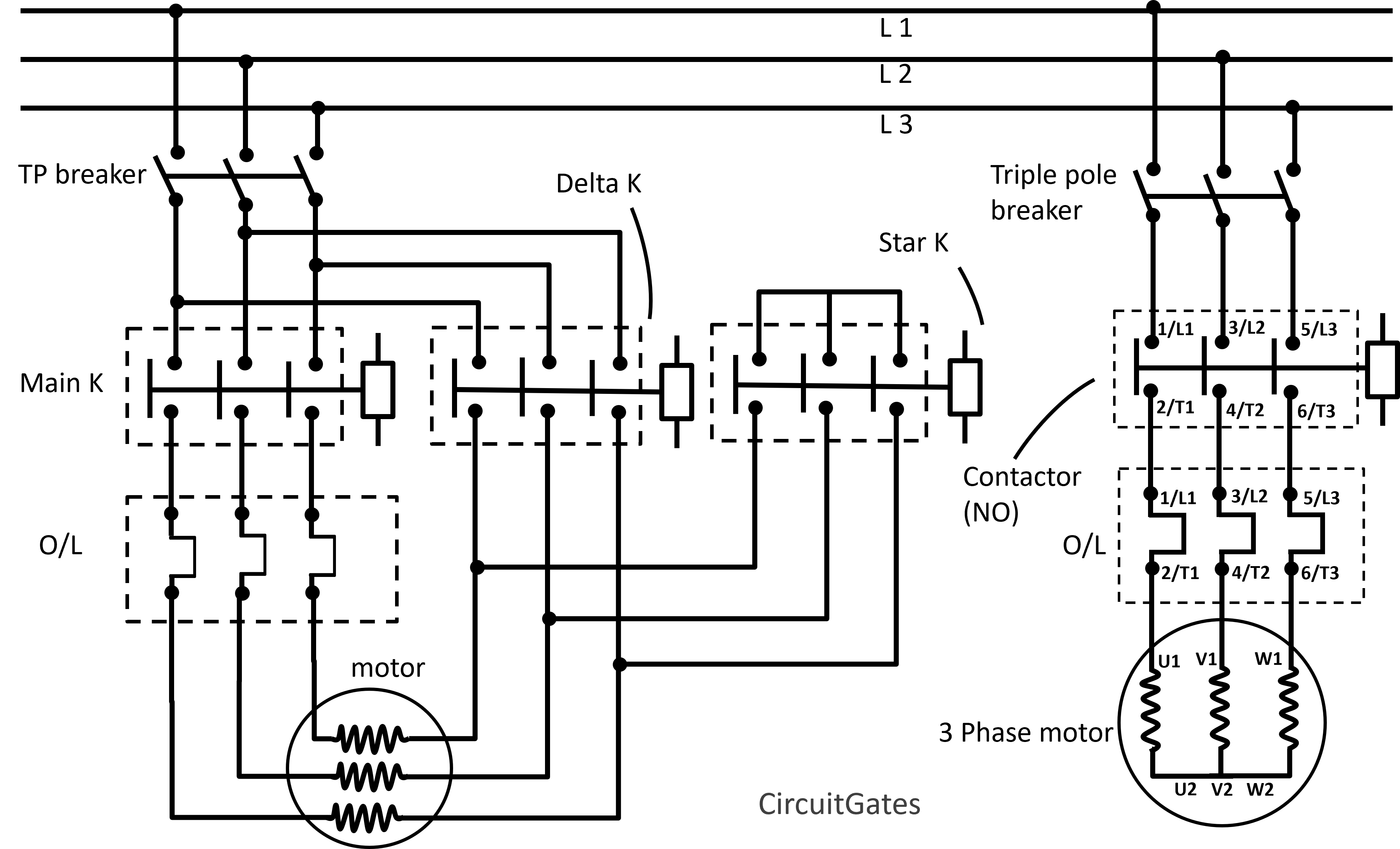
The diagrams below show the power and control circuits of the sequential electric motor starting we previously discussed. The explanation on how it works follows.
Power Circuit
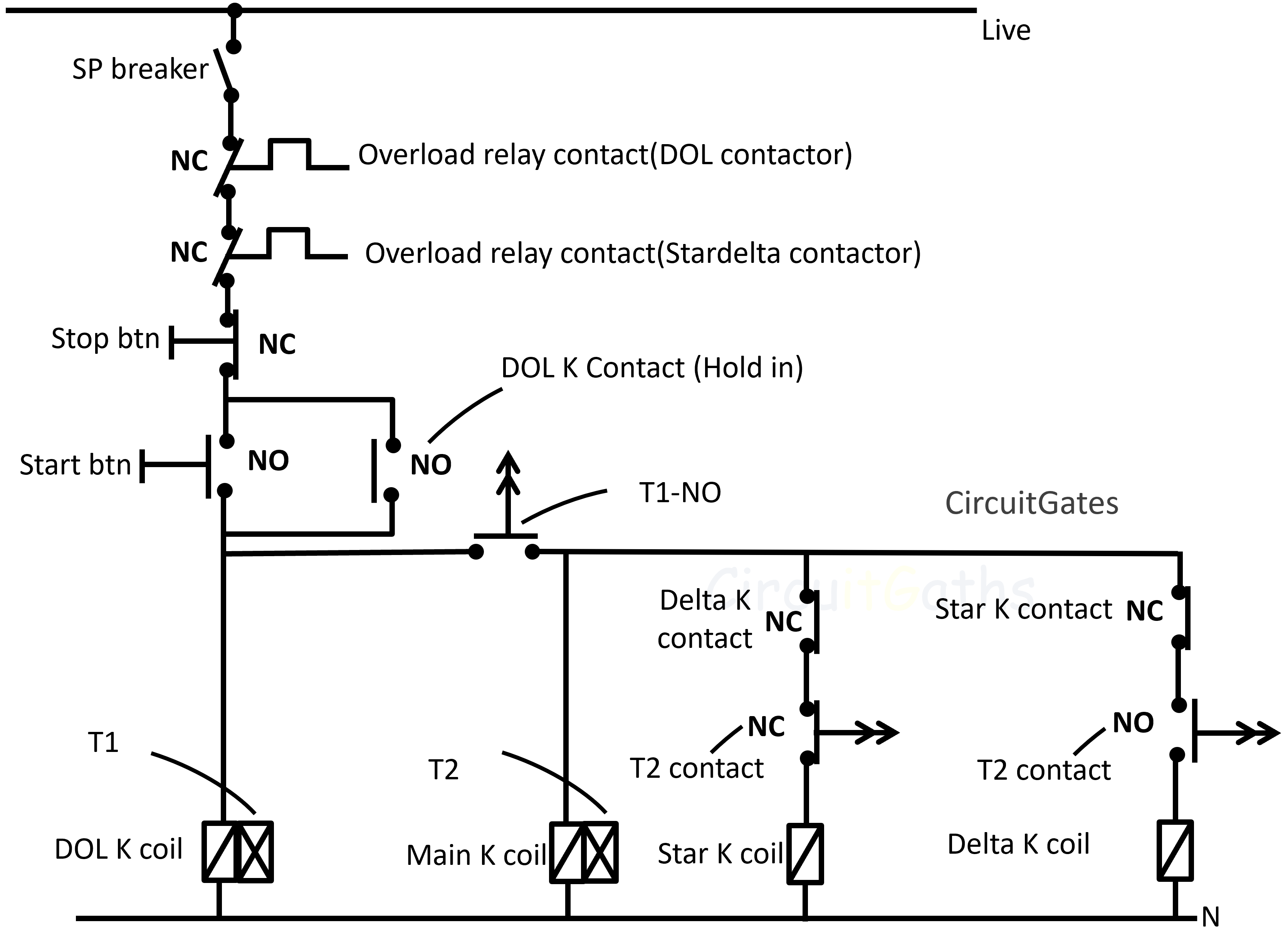
Control Circuit
- TP Breaker - Tripple pole breaker
- SP Breaker - Single pole breaker
- K - Contactor
- btn - Button
- NC - Normally closed
- N - Neutral
- O/L - Overload relay
- NO - Normally open
- T1 - Timer one
- T2 - Timer two
Key
Explanation
In this article, we are not covering how various parts of the circuits work, as we have already discussed them in the articles on how a direct online and stardelta starters work.
We are only looking at how the sequential electric motor starting works.
On the control circuit of a sequential electric motor starting, we have two pneumatic timers. One labeled T2 is for switching the star-delta electric motor from star to delta.
The other labeled T1, is for putting the crushing machine electric motor in the ON position after the DOL electric motor has run first for four seconds.
To start running the electric motors, the start button is pressed. This allows current to flow through the DOL electric motor contactor coil.
When current flows through the DOL electric motor contactor coil, the DOL contactor power contacts are put into the closed position, resulting in power reaching the DOL electric motor and it starts running.
The T1 timer is connected in a way such that it goes into ON position when the DOL motor begins to run. As the DOL motor starts running, the T1 timer is switched to the ON position.
The timer T1 counts up to four seconds and closes the contact connecting the star-delta electric motor control circuit labeled "T1-NO", and the stardelta electric motor begins to run.
We have already covered how a star-delta starter works, you can check it out.
In the previous control circuit diagram, we used a timer to put the star-delta electric motor in the ON position, there is another way do it.
The following are two separate control circuits for the sequential starting of electric motors.
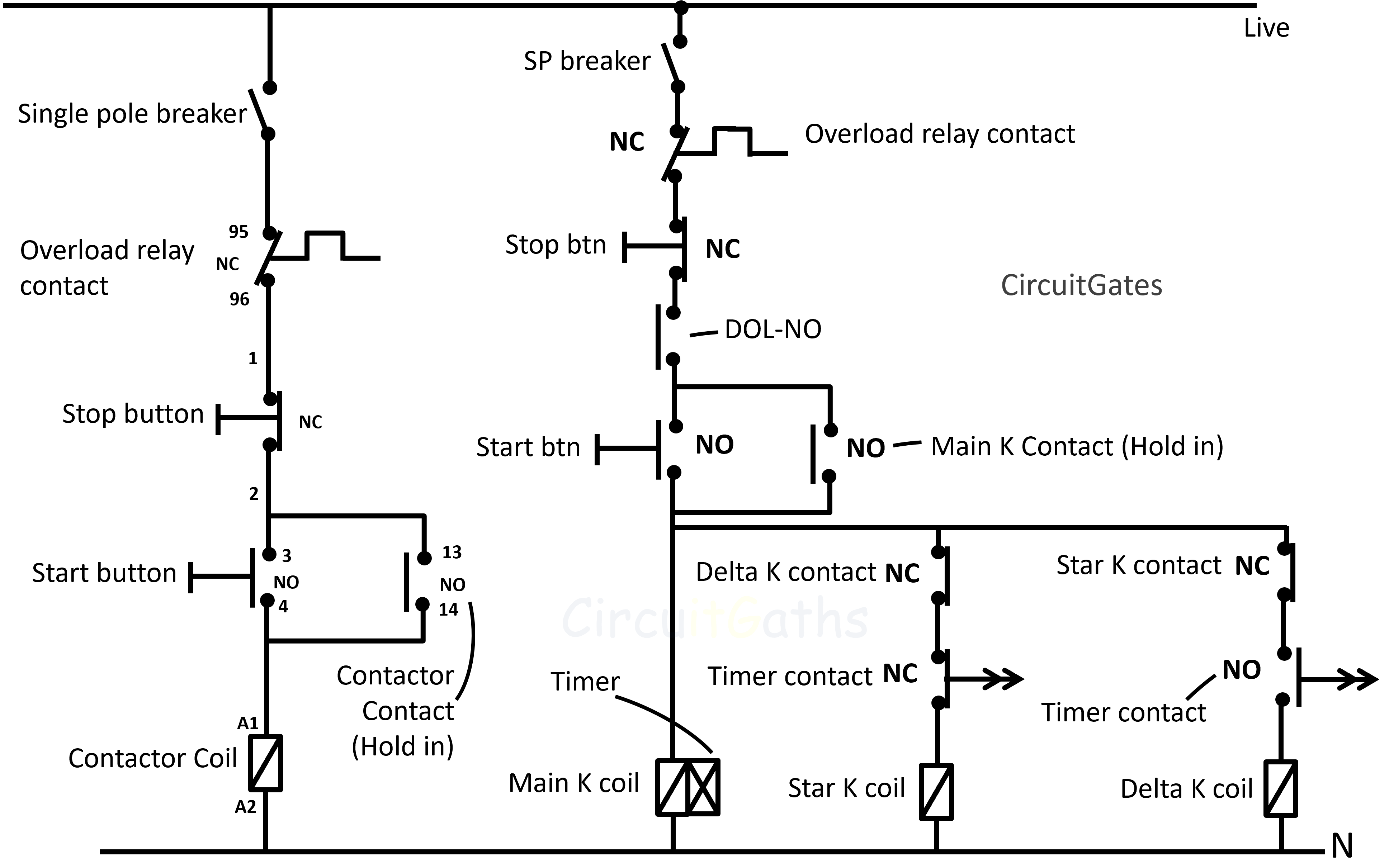
- DOL-NO - Interlock (normal open)
Key
The control circuit of a star-delta starter is connected through the normally open contact labeled "DOL-NO" of a DOL contactor, such that when the DOL is OFF, this contact is open and the star-delta motor can't start.
When the DOL motor is running, the contact "DOL-NO" closes, such that when the start button of star-delta starter is pressed, current can pass through allowing the star-delta electric motor to run.
Using the latter control circuits, the star-delta electric motor will not automatically start after the DOL runs for four seconds as in the earlier control circuit diagram.
The operator is needed to switch the star-delta electric motor ON after first switching ON the DOL electric motor.