Star and Delta Configurations Explained
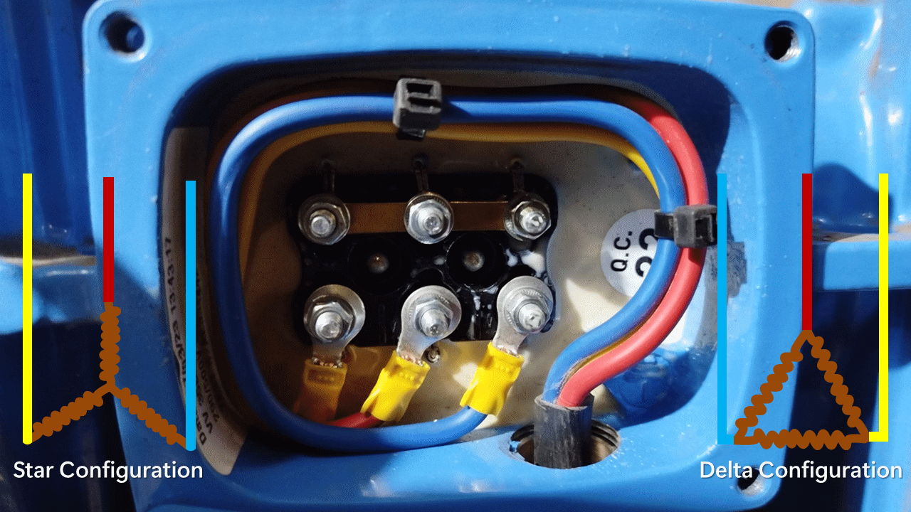
Star and delta configurations are methods for connecting three-phase loads and generators to make the circuit complete and enable current flow.
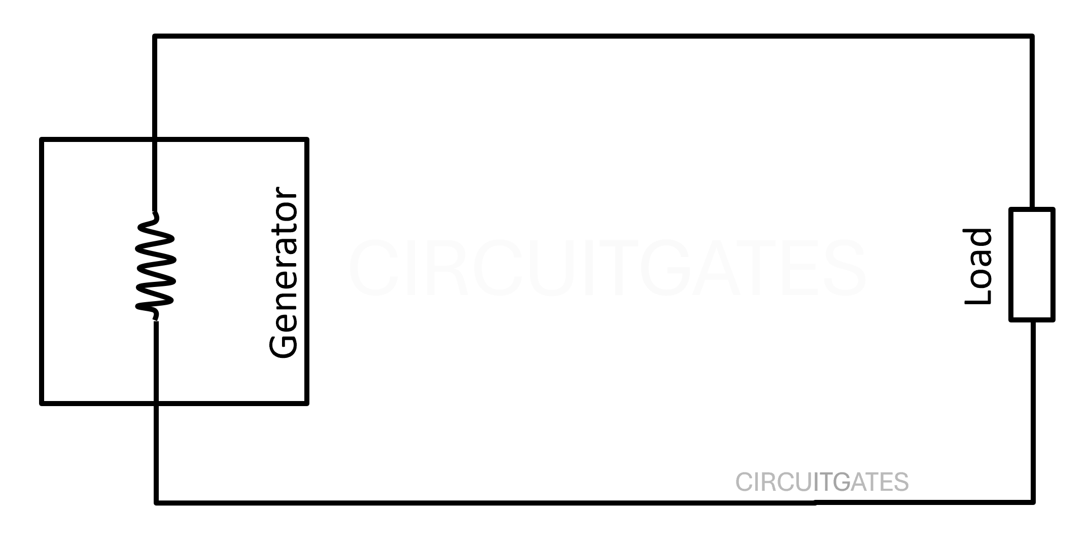
Current flows in a complete or a closed circuit. In single-phase loads and generators, we connect the live wire from the generator or battery in DC to the load, and then the neutral from the load back to the generator.
In a single-phase generator, the live wire supplies current to the load and the neutral forms a return path for current from the load back to the supply, thus forming a complete circuit as in the following diagram.
Let's look at a three-phase load. A three-phase load is a load with three separate loads contained in it as shown in the following diagram.
To make a complete circuit for each load contained in a three-phase load, we need to run three separate live and neutral conductors as shown in the following diagram.
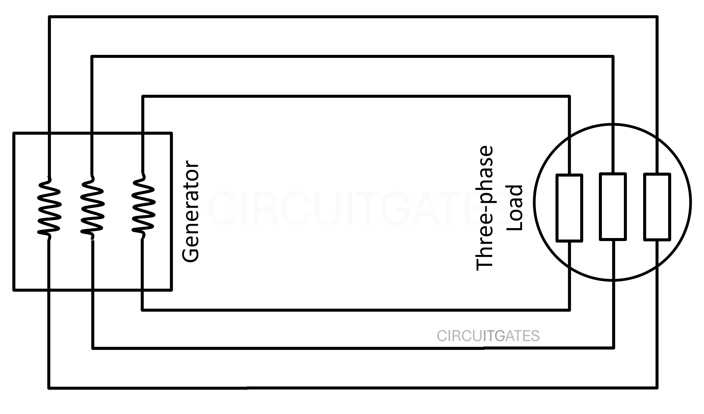
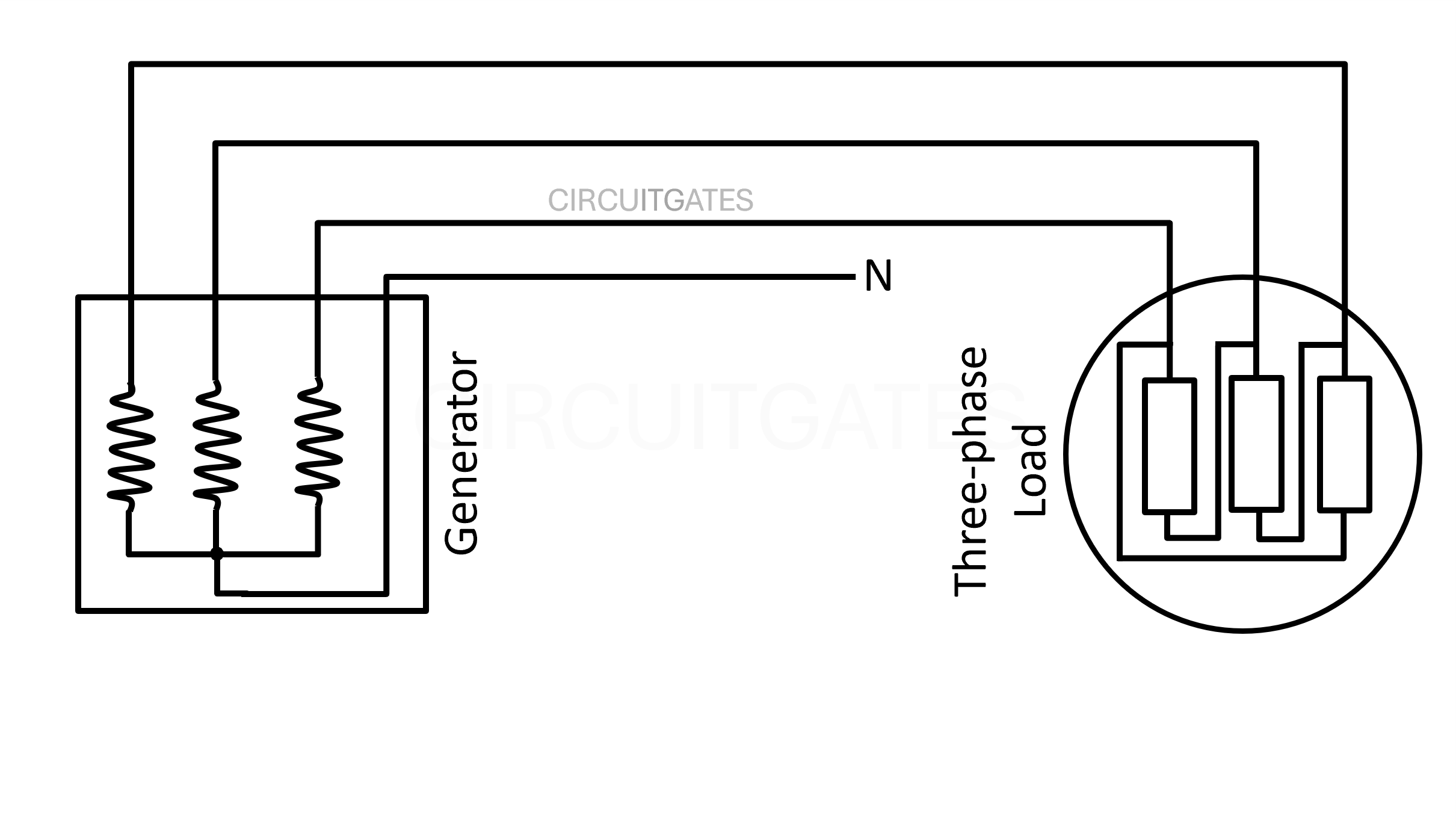
As you can see in the previous diagram, there are more conductors (six conductors) that are used to make the circuit for a three-phase load complete. We can reduce these cables by connecting the three-phase loads and generators in star or delta as shown in the following diagram.
In the following diagram, the generator is connected in star and the load is connected in delta.
The star and delta configurations enable the three-phase conductors to share their current allowing current to flow from the generator to the load and then back to the generator, thus making the circuit complete.
Star Configuration
In a star configuration, the three phases are connected to the loads or coils and after the loads or coils, they are joined together.
In a star configuration, if the three loads or coils of a three-phase load are not of the same size or not balanced, we add a neutral wire so that extra current will use the neutral conductor back to the supply.
The neutral wire also enables the connection of single phase loads by connecting them to the neutral and any other phase conductor.
Delta Configuration
In a delta connection, the three phases are connected to the loads, and the phase from each load is connected to the start of the next load.
Now that we have find a way to reduce the number of cables, there are issues that arise in star and delta configurations due to differences in arrangement which lead them to have some different applications.
For example, in star configuration we can have a neutral for connection of single-phase loads, so star configurations are most used on the secondary side of distribution transformers to connect single-phase loads.
The star configuration has a higher impedance (resistance + reactance) to the line voltage than a delta configuration. That is why a star configuration is used to start a larger electric motor, and then the delta runs the electric motor.
Let's look at line voltage, phase voltage, line current and phase current in star and delta configurations for balanced load, where there is no need for a neutral wire.
Current, Voltage, and Impedance in Star and Delta Configurations
In order to understand star and delta differences in current, voltage and impedance, we first need to understand line voltage, phase voltage, line current, and phase current in three-phase systems.
Line voltage (VL) is the voltage that drives current from one live conductor, through the load, to another live conductor as in the following diagram. We can say line voltage is the voltage between two live conductors.
Phase voltage (VP) is the voltage across one coil or load of a three-phase load, or it is the voltage that drives current through one coil or load of a three-phase load as shown in the following diagram.
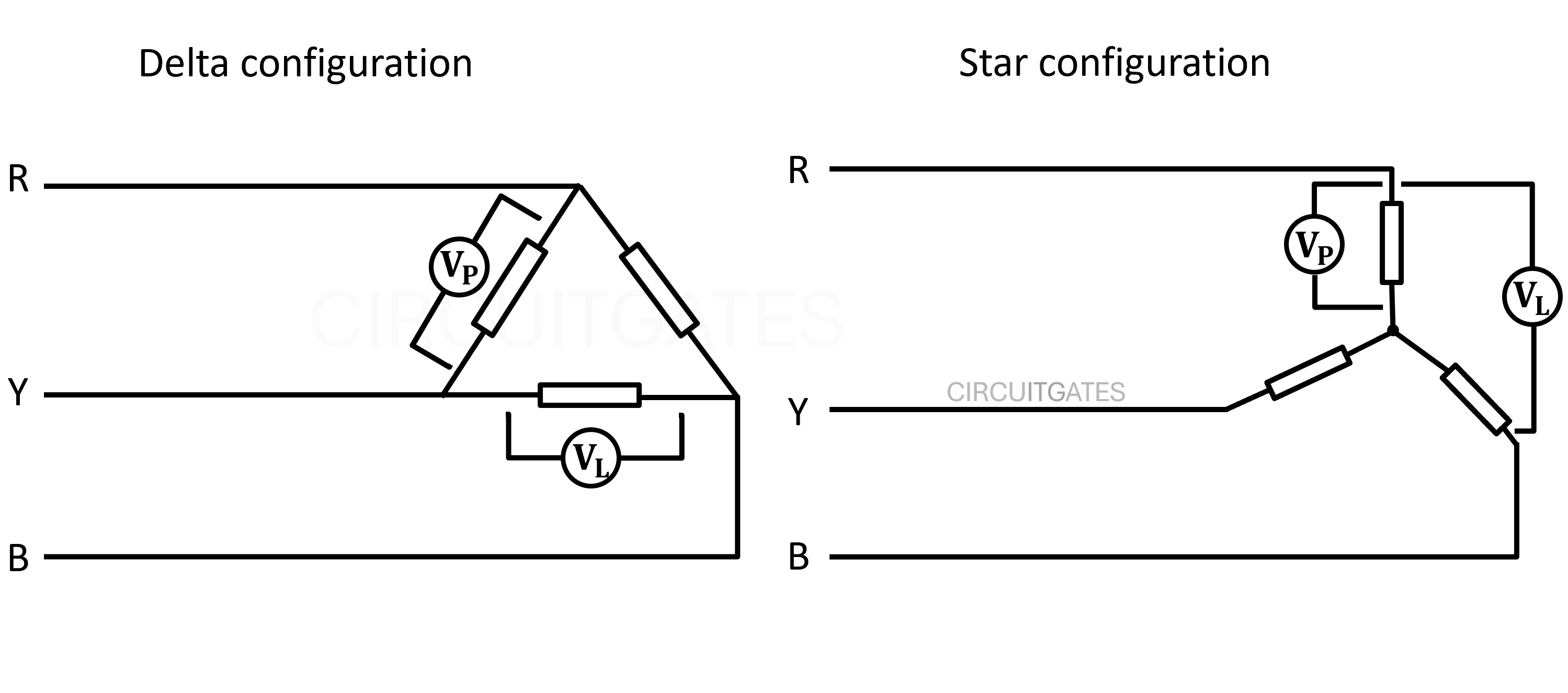
Line current (IL) in star and delta configurations is the current measured in a live conductor.
Phase current (IP) in star and delta configurations is the current measured in one of the coils or loads of a three-phase load.
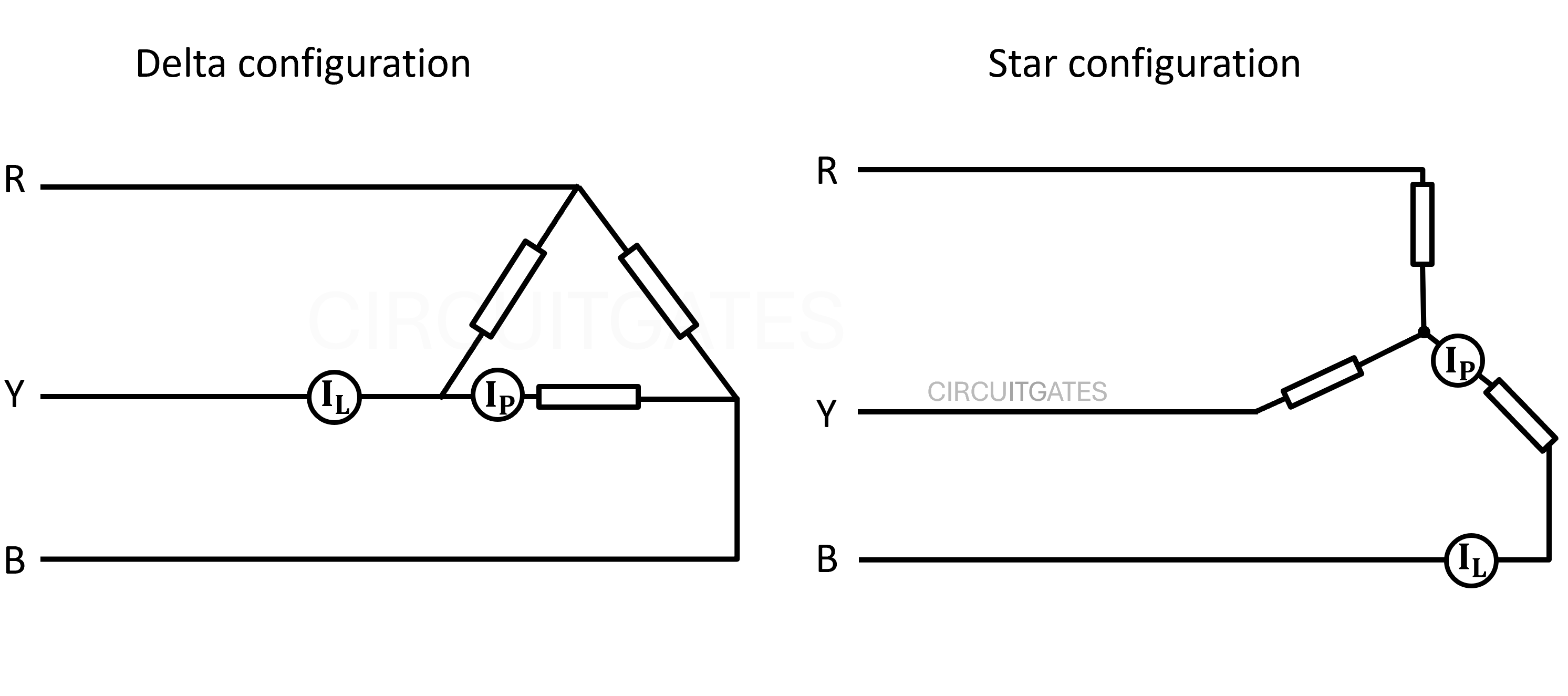
In the previous illustrations we can see that:
In a Delta Configuration
Line voltage is the same as phase voltage because the delta configuration has only one coil or load between two live conductors.
Line current is different from phase current because the line current splits into two phase currents at each junction. Line current is measured before the split, while phase current is measured in each coil after split.
Therefore, the line current is higher than phase current in a delta configuration.
In a Star Configuration
Line voltage is different from phase voltage because phase voltage is the voltage that drives current through one coil or load of a three-phase load whereas line voltage is the voltage that drives current through the two coils or loads of a three-phase load.
Therefore, the line voltage is higher than the phase voltage in a star configuration.
Line current is the same as phase current because both are in a one conductor with no splits.
Conclusion: In the arrangement of the two configurations, you can see that in star the current flowing from one live conductor to the other live conductor is through two coils and in delta it is through one coil.
OR
In star, current flows from one live conductor to another through two coils in series. In delta, it flows through only one coil.
Therefore, a star configuration has a higher impedance than a delta configuration.
Newsletter
Never miss a chance to learn something new with CircuitGates, subscribe to our newsletter
By subscribing, you agree to our Terms of use and Privacy policy.