What Power Factor is and How Power Factor is Corrected
Power Factor
Power factor is the ratio of real (active) power to apparent power. Power factor is a ratio, so it does not have units.
In electrical engineering, the term power is too general. Power falls into three categories that are real power, apparent power and reactive power.
Apparent Power (S)
Apparent power is the total power drawn from the supply by the consumer, e.g. an industry. It is usually the one measured by suppliers' energy meters on the consumer's site. Apparent power is measured in volt-ampere (VA), or kilovolt-ampere (kVA) when working with large values of power.
Transformer rating is done in kVA , which means apparent is its rating.
Real Power / Active Power (P)
Real or active power is the part of apparent power drawn from the supply that does work for us, like lighting up a fluorescent lamp, rotating an electric motor.
Real power is measured in watts (W) or kilowatts (kW) when working with large values of power.
Reactive Power (Q)
Reactive power is a part of apparent power that must be present in some loads such as electric motors and fluorescent lamps for real power to do work for us. Reactive power doesn't do work for us. We will understand why shortly.
Reactive power is measured in volt-ampere reactive (VAr) or kilovolt-ampere reactive (kVAr) when dealing with large values of power.
Since we said reactive and real power are part of apparent power, apparent power is a combination of real power and reactive power.
Since power factor is the ratio of active power to apparent power, or real power divided by apparent power, then its highest value is one.
If power factor is one, it means real power is equal to apparent power and reactive power is zero, which happens in DC and also in AC when powering some types of loads. We will understand this shortly.
To understand where these power names are coming from, we need to understand the types of electrical loads and DC vs AC electricity.
We basically have three types of loads that are resistive loads, capacitive loads and inductive loads. Some loads can be inductive, capacitive and resistive at the same time.
These loads oppose the flow of current in different ways. The opposition given to the flow of current by resistive loads is called resistance.
The opposition given to the flow of current by inductive loads is called inductive reactance, and the opposition given to the flow of current by capacitive loads is called capacitive reactance.
If a load is resistive, inductive, and capacitive at the same time, the opposition it gives to the flow of current is called impedance.
The way these three different loads oppose the flow of current has effects to the flow of current and voltage. Current and voltage in a circuit must increase or decrease proportionally (must be in phase), but some of these loads alter this.
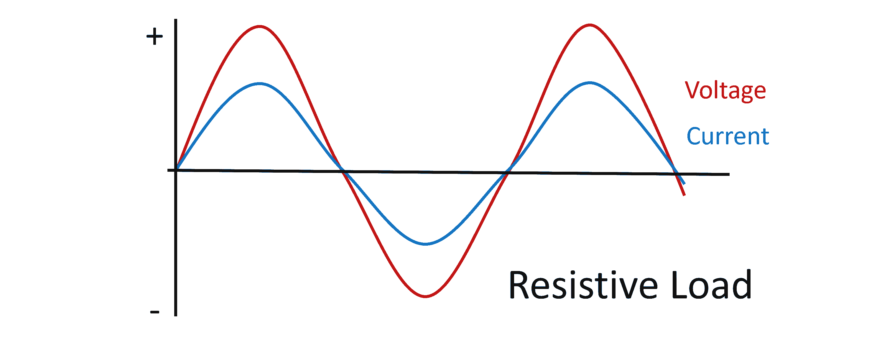
Resistive loads only reduce the amount of current flowing in a circuit but keep the current and voltage in phase.
Inductive and capacitive loads are the ones that alter the proportional increase or decrease of voltage and current, since they oppose the flow of current by storing and releasing energy.
Let's move on to types of electricity, and we will come back to electrical loads. We have two types of electricity: DC and AC.
Direct Current Electricity is the type of electricity in which current and voltage flow in the same direction with constant magnitude.
Alternating Current Electricity is the type of electricity in which current and voltage continually change in magnitude and direction.
Since DC flows in one direction with a constant magnitude, inductive and capacitive loads only oppose current flow during switching-on, when they store energy to full capacity. The inductive and capacitive loads have no effect on the flow of current and voltage in DC.
In a capacitive load, DC current and voltage will eventualy stop flowing when the load stores energy to full capacity, while an inductive load, stops opposing DC once it stores energy to full capacity.
In AC, current and voltage constantly change in magnitude and direction of flow 60 or 50 times per second depending on the frequency, and this causes the inductive and caapacitive loads to continually oppose current flow by continually storing and releasing energy.
The way the inductive and capacitive loads oppose the flow of current causes the current and voltage to be out of phase in different ways.
The capacitive load causes the current to lead the voltage, while the inductive load causes the current to lag behind the voltage.
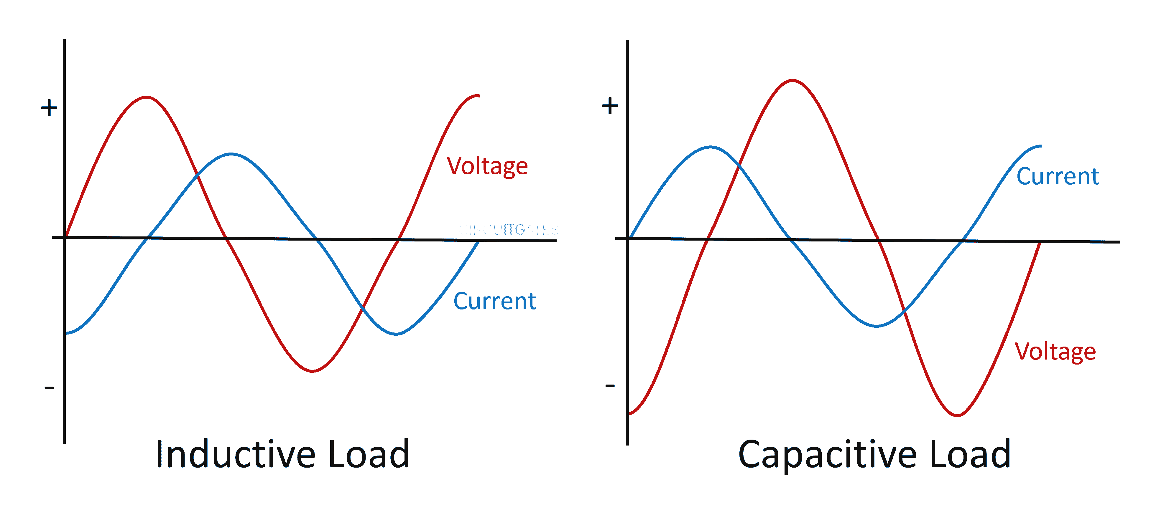
In the previous graph of the capacitive load, you can see that the current line is the one that first reaches the peak in the first positive half-cycle before voltage, this means current is leading voltage.
In the inductive load graph, voltage first reaches the peak in the positive half-cycle before current, in this way we say current is lagging behind voltage in inductive loads.
Inductive and capacitive loads just store energy and then return it to the supply, unlike the resistive loads that convert the energy into heat, like a filament lamp.
In industrial sites, we have loads such as electric motors that are inductive and resistive at the same time.
These loads have a reactive part that stores energy from the supply and then returns it to the supply, and the resistive part that converts the energy into mechanical energy to do work for us.
The energy stored by the reactive part is also important since it is the one that creates the magnetic field that causes the electric motor to rotate, but this energy will then be returned to the supply.
Since the energy is stored and returned back to the supply, it passes through the energy meter of the consumer, so is regarded as energy used by the consumer, although it then returns to the supply.
If the industrial site contains a lot of these loads, they will cause a lot of reactive power demand, which will then increase current, overloading the supplier's power supply and result in damage to the supplier's components.
Reactive power is not bad power, but it is power that must be catered for by the industry not by the supplier. Power factor is the one that can be bad.
The industry must correct its power factor, where it tries to make apparent power equal to real power at its energy meter by employing power factor correction methods.
Methods of Correcting Power Factor
There are several ways of correcting the power factor, including the use of capacitor banks, synchronous motors and phase advancers.
In this article, we will look at capacitor banks because they are the most commonly used method in industries to correct power factor.
Adding Capacitor Banks
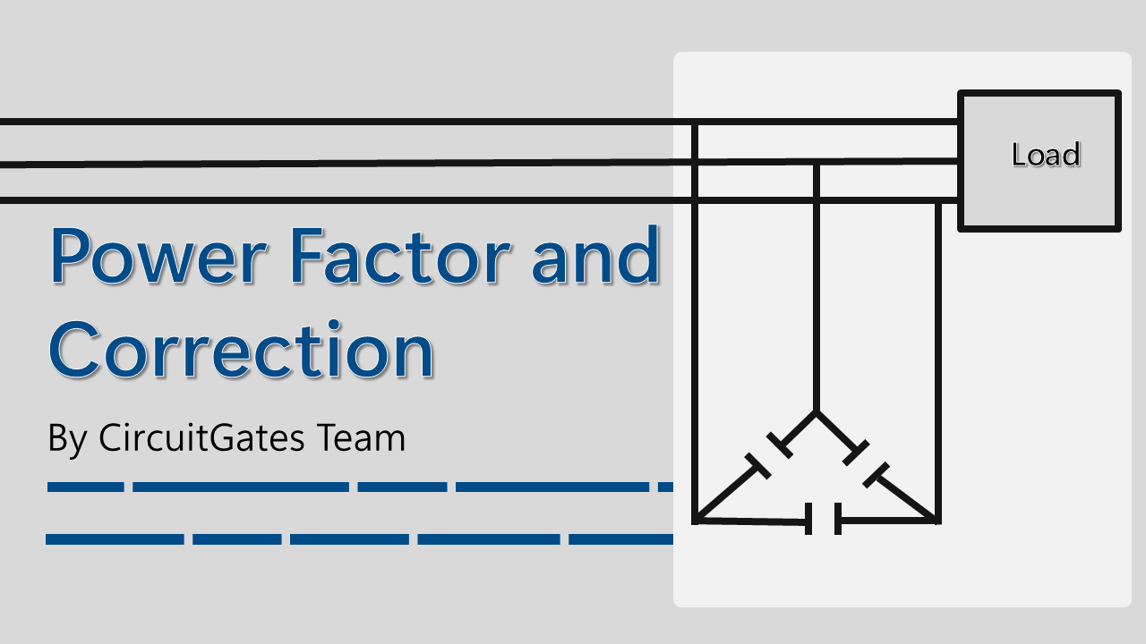
To correct the power factor using capacitor banks (groups of capacitors), capacitor banks are connected across the load.
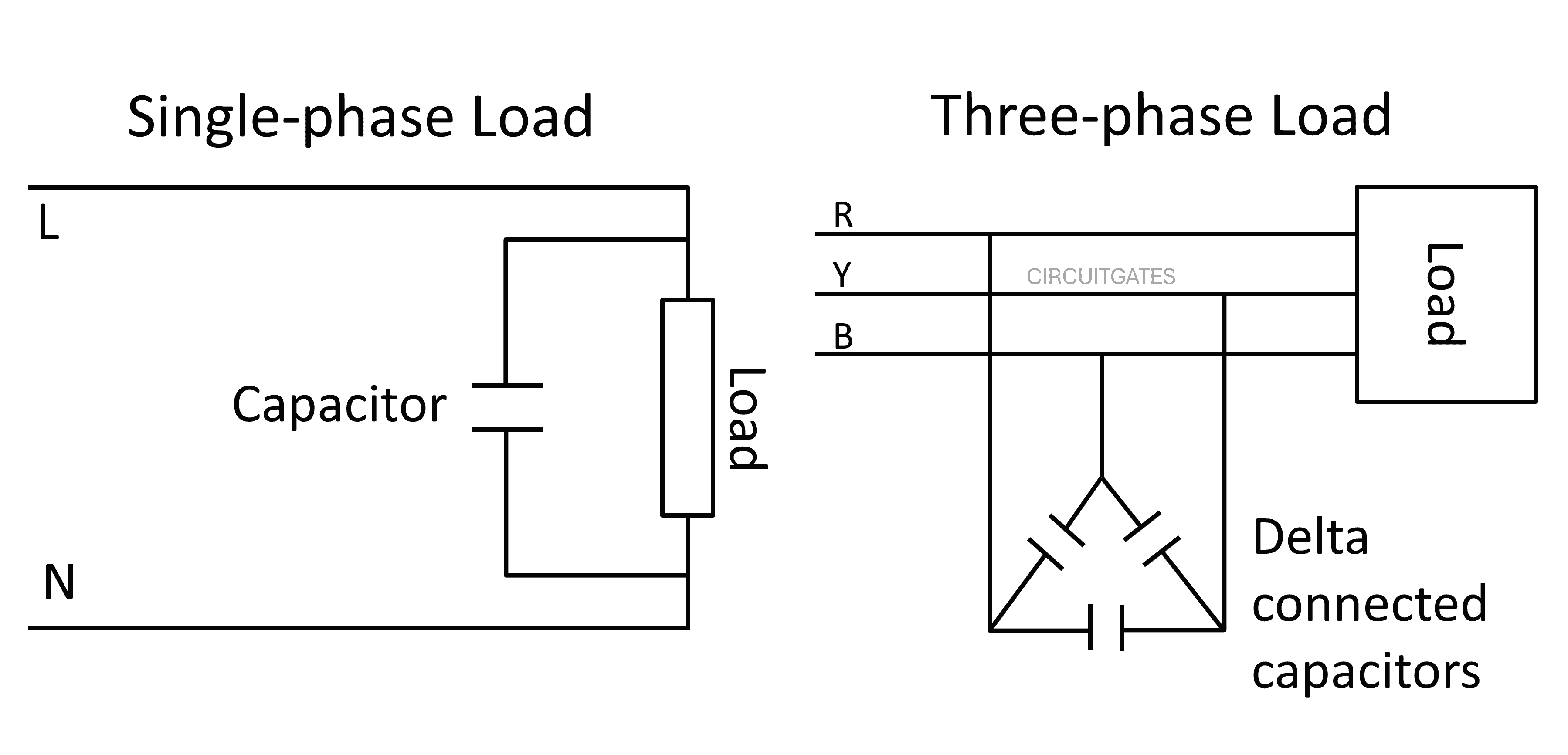
In the following diagram, for a single-phase load we just connected a single capacitor across the load. For a three-phase load, we connected three capacitors in delta configuration across the load.
Since inductive loads cause the current to lag behind voltage and capacitive loads cause the current to lead voltage, adding capacitors across the inductive load will cause the supply voltage and current to be back in phase.
It is like energy being released by the inductive load is going to the capacitor and stored, not to the supply. The energy will then be released by the capacitor and stored by an inductive load, and process reoccurs again and again.
It is a good practice to use motors with ratings and features well suited to their function, since the power factor changes with motor load.